Where does End-to-End QoS actually materialize?
Beyond abstract 5QI definitions and policy rules in the Core, QoS becomes real only when data flows through the entire network stack — from Application servers through the Core and down to RAN schedulers, where packets are finally transmitted over the air.
This post walks through each stage to reveal how 5G turns high-level QoS rules into concrete packet behavior across the network.
📌 Overall Downlink Path Summary
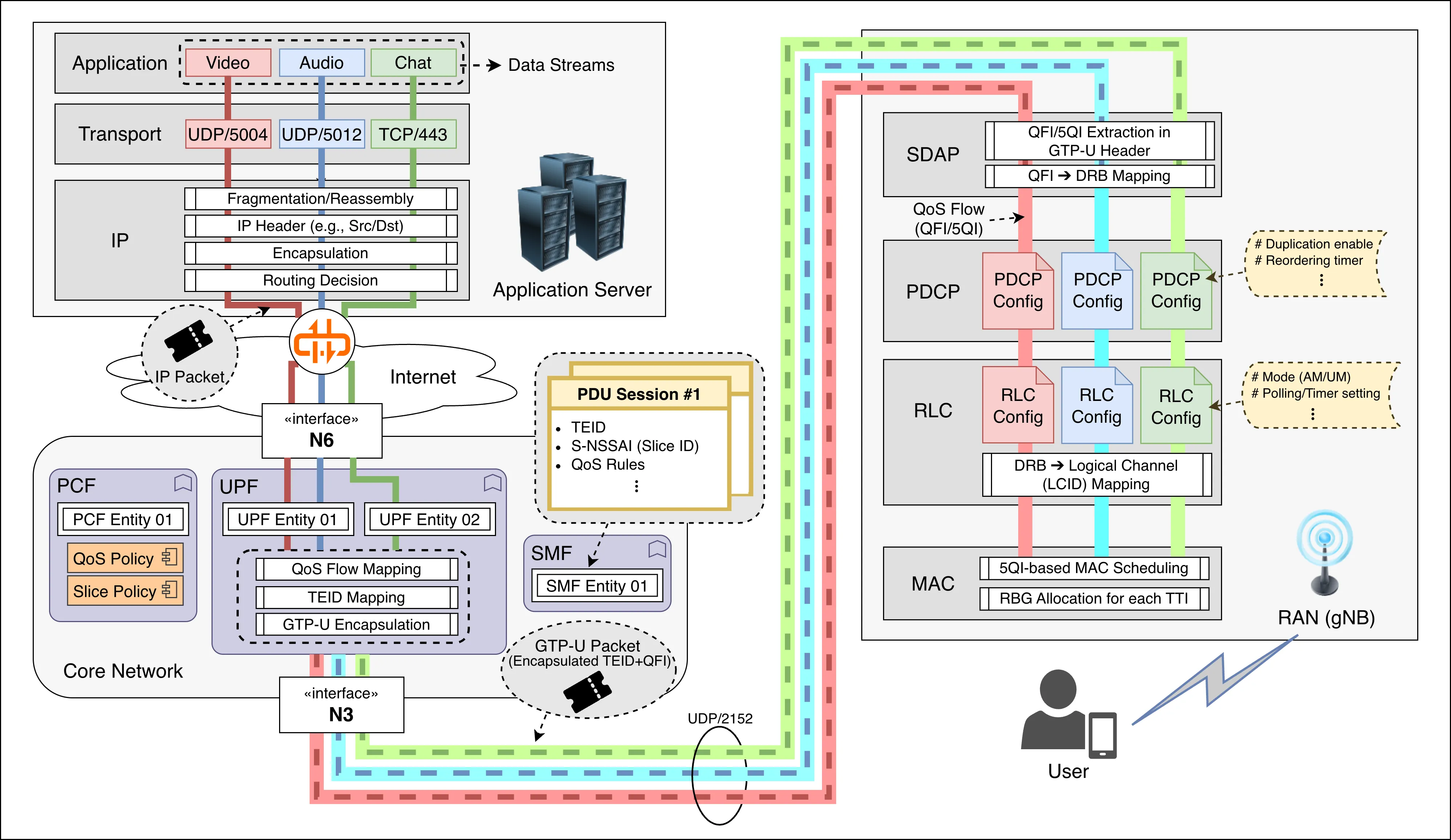 Multi-flow E2E Data Transmission in 5G Downlink. Three application flows (Video, Audio, Chat) traverse the network stack independently, each mapped to distinct QoS Flows (QFI) at the UPF, then to separate DRBs at the RAN, where MAC scheduling finally allocates radio resources according to 5QI-based priorities.
| Step | Network Domain | Transmission Unit | Control Mechanism |
|---|---|---|---|
| ① Application Server | App domain | App data | TCP/UDP |
| ② Internet Backbone | Public / MNO AS | IP packet | hop-by-hop routing |
| ③ UPF ingress (Core entry) | Core domain | IP packet | PDR/FAR/QER matching |
| ④ UPF egress | Core → RAN | GTP-U encapsulated packet | HTB / DRR / WFQ scheduling |
| ⑤ RAN (gNB) | Access domain | MAC/RLC PDU | PF / RR / RL-based |
| ⑥ UE | Device domain | App data | TCP/UDP delivery |
1️⃣ Application Traffic Generation
A single application server generates and delivers multiple types of traffic for service delivery.
For example, in a video conferencing application such as Zoom or Google Meet:
| Function | Transport Type | Protocol / Port Example | QoS Characteristics |
|---|---|---|---|
| Video stream | UDP RTP | port 5004 | high throughput, low delay |
| Audio stream | UDP RTP | port 5006 | low delay, small packet |
| Chat message | TCP | port 443 (WebSocket) | best effort |
| Screen sharing | UDP/TCP | ports 3478–3480 (STUN/TURN) | moderate bitrate |
| Control signaling | TCP | port 443 | infrequent |
Depending on transport type and QoS characteristics, multiple traffic types are sent, and each of them forms one Transport Flow ➔ IP Flow.
-
The application server (e.g., YouTube, Zoom, Cloud, etc.) sends data (HTTP, RTP, etc.) to the Transport Layer (TCP/UDP), and the OS network stack encapsulates it into an IP packet
[IP header (dst = UE IP)] [TCP/UDP header] [Payload] -
In the Core, traffic is classified by Transport Flow (5-tuple)
(src IP, dst IP, src port, dst port, protocol) -
Even within a single application, if multiple ports, protocols, or sub-channels are used, the Core network treats them as multiple IP flows.
Congestion Control in Transport Layer
Transport Congestion Control (CC) determines how fast the application injects data into the network. The sending rate and pacing behavior directly influence latency, jitter, and loss observed along the path.
⚙️ Common Algorithms
- CUBIC: Loss-based CC, widely deployed (Linux default). Aggressively increases sending rate until packet loss occurs.
- BBR (Bottleneck Bandwidth and RTT): Model-based CC developed by Google. Estimates available bandwidth and minimum RTT to avoid excessive queuing.
- NewReno: Classic loss-based approach, conservative but stable.
2️⃣ Internet Routing
- The generated IP packets travel hop-by-hop through the public Internet.
- They pass through multiple routers, IXs (Internet Exchanges), and transit providers before reaching the MNO’s Core Network entry (UPF N6) corresponding to the UE.
Global Routing Table (MNO Backbone)
- Each MNO operates its own backbone (AS, Autonomous System), meaning that the internal Internet routing structure differs by operator:
- Vodafone → AS3209
- Deutsche Telekom → AS3320
- Telefónica O2 → AS6805
- Each packet follows the routing table within the MNO’s Internet backbone, which directs packets to the UPF belonging to the UE’s network:
- The UPF advertises its reachable IP prefixes via BGP (“send traffic for this IP to me”).
- Routers within the MNO core register the UPF’s N6 interface IP as the next hop in their routing tables.
- External Internet packets are then forwarded hop-by-hop until they reach the UPF’s N6 IP address.
3️⃣ UPF Forwarding in Core Networks
Once IP flows reach the UPF, packets go through the following steps before being forwarded to the target gNB:
- The UPF identifies the PDU Session based on the packet’s UE IP address.
- According to the PDR (Packet Detection Rule) configured by the SMF, the UPF determines which QoS Flow (QFI) the packet belongs to.
- The QFI is derived from QoS parameters such as 5QI, GBR, and ARP.
- The UPF encapsulates the packet with a GTP-U header containing the QFI and TEID (Tunnel Endpoint ID) (as defined in 3GPP TS 29.281 §5.3)
- The UPF forwards the GTP-U encapsulated packet to the RAN (target gNB) via the N3 interface.
UPF Routing Table
| Type | Owner | Main Function | Example |
|---|---|---|---|
| ① Global Routing Table (MNO Backbone) | MNO Core Router / Aggregation Router | Determines which UPF to forward incoming Internet packets to | “10.10.0.0/16 → UPF_MUC_01” |
| ② Local Routing Table (UPF Entity) | Inside UPF server / VM / container | Forwards packets either to RAN (gNB) or external network (N6) | “RAN subnet → dev n3”, “0.0.0.0/0 → dev n6” |
UPF Functional Pipeline
| Stage | Processing Task | Responsible Entity |
|---|---|---|
| Ingress (N6) | Match incoming IP packets with PDR / FAR rules | UPF Core |
| Routing lookup | Determine which RAN tunnel (N3) corresponds to the UE IP | UPF local route table |
| QoS handling | Apply HTB / DRR scheduling per QFI | UPF scheduler |
| Encapsulation | Add GTP-U header (TEID, RAN endpoint) | UPF |
| Egress (N3) | Forward packet to gNB | UPF via local routing interface |
*️⃣ IP Flow ⇔ QoS Flow Mapping
The mapping between an IP flow and its corresponding QoS Flow (QFI) is pre-defined by SMF policies. The UPF then determines which QFI each incoming IP packet belongs to.
5G QoS Hierarchy
| Level | Entity | Unit | Description |
|---|---|---|---|
| QoS Policy Level | PCF (Policy Control Function) | 5QI | Defines service class (delay, reliability, etc.) |
| Session / Flow Management | SMF (Session Management Function) | QFI | Determines which flow belongs to which QoS Flow (QFI) |
| Bearer Mapping / Enforcement | UPF + RAN (SDAP, scheduler) | QFI → DRB | Executes traffic handling (queueing, transmission) |
QoS Flow — The Smallest QoS Unit Defined in the 5G Core
A QoS Flow is the finest-grained QoS entity defined by the 5G Core. Each flow is associated with a unique QFI (QoS Flow Identifier) and a set of 5QI-based QoS parameters such as PDB, PER, and GFBR.
- A single PDU Session may contain multiple QoS Flows.
- Each flow is assigned a 5QI that reflects its service characteristics (e.g., VoIP, URLLC command, video stream), and therefore inherits the QoS policy defined for that 5QI.
- Upon receiving packets, the UPF classifies them by determining which QoS Flow (QFI) each packet belongs to and forwards them to the RAN accordingly.
PCF — “QoS Class Designer”
📘 PCF = Policy engine that defines and provides QoS policies
- Owns the global QoS policy database of the network
- Interprets QoS rules dynamically based on subscriber info (UDR/UDM) and slice info (S-NSSAI)
- Defines the QoS parameter set (QoS Characteristics) for each 5QI (e.g., 5QI=1 → URLLC, 5QI=8 → Video Streaming)
➡️ Serves as a context-aware policy engine, not a static table
SMF — “Flow-to-QoS Flow Mapper”
📘 SMF = The manager that constructs actual QoS mappings
- When creating a PDU Session, SMF receives QoS policies (5QI, etc.) from the PCF
- Maps each IP Flow to a QFI based on packet filters (5-tuple, application type, etc.)
- Generates and assigns QFI IDs and associates them with their corresponding 5QIs
- Distributes mapping info to both:
- RAN (Control Plane) via RRC signaling (DRB + QFI/5QI mapping)
- UPF (User Plane) via PDR/FAR/QER configuration for packet classification and QoS enforcement
Example👇
| Flow | 5QI | QFI | Description |
|---|---|---|---|
| UDP:5004 (video) | 8 | 5 | Streaming QoS Flow |
| TCP:443 (web) | 9 | 6 | Best-effort QoS Flow |
| UDP:5012 (voice) | 7 | 7 | Conversational QoS Flow |
➡️ The SMF acts as a central distributor, deploying QoS policies at the session level.
UPF — “QoS Flow Enforcer”
📘 UPF = The executor that applies QoS in the data plane
- Classifies and handles packets based on PDR (Packet Detection Rule), FAR (Forwarding Action Rule), and QER (QoS Enforcement Rule) received from the SMF:
- PDR: Identifies which QFI (QoS Flow) a packet belongs to
- FAR: Defines forwarding, dropping, or duplication actions
- QER: Applies rate limits, burst size, and marking policies
- Encapsulates packets with GTP-U headers including QFI, then forwards them to the RAN (gNB)
➡️ The UPF functions as a QoS enforcement engine, performing queueing, rate control, and forwarding per QoS Flow.
gNB SDAP Layer
📘 SDAP = The orchestrator that binds QoS Flows to radio bearers
- The SDAP layer in gNB (and UE) interprets the QFI from the GTP-U header and maps it to the corresponding DRB (Data Radio Bearer)
- Each DRB forms a logical bearer stack (PDCP–RLC–MAC) for transmission
SDAP responsibilities
1️⃣ Map QoS Flows (QFIs) to DRBs
2️⃣ Propagate QoS properties (delay, reliability, priority) to lower layers
QoS reflection by layer
- PDCP: duplication, reordering, header compression
- RLC: AM/UM mode, buffer size, discard timer
- MAC: scheduling weight, MCS/HARQ adaptation
➡️ SDAP serves as a control gateway linking QoS Flows to the full radio bearer stack (PDCP–RLC–MAC) for real QoS execution.
*️⃣ PDU Session
A PDU Session is a logical IP session established between the UE and the Core Network. Each session represents a GTP-U tunnel (UE ↔ UPF) defined by the following configuration set.
PDU Session Configuration
- TEID (Tunnel Endpoint ID) : Unique identifier for a GTP-U tunnel; used by the UPF and gNB to identify the session and demultiplex packets to the correct QoS Flow.
- S-NSSAI (Slice ID) : Identifies the network slice to which the session belongs.
- DNN (Data Network Name) : Target data network (e.g., Internet, MEC, or private).
- UE IP Address : IP assigned to the UE; serves as the destination IP in downlink packets.
- Core Network : The core domain of the connected MNO (e.g., specific 5GC domain).
- PDU Type : IPv4 / IPv6 / Ethernet.
- UPF 경로 : The UPF chain traversed by the session (e.g., Edge → Central UPF); each GTP-U tunnel is uniquely identified by its TEID.
- QoS Rules : QoS Flow mappings (QFI/5QI) assigned by the SMF according to PCF policies.
➡️ All QoS Flows following this configuration belong to and are managed under the same PDU Session.
UE ↔ Core Relationship
- Each PDU Session is uniquely bound to one UE and one Core Network.
- A single UE can maintain multiple PDU Sessions with the same core network, each with its own configuration set.
- QoS policies, UPF paths, IP addresses, and PDU types
Slice-based PDU Session Isolation
| Perspective | Effect |
|---|---|
| QoS Separation | URLLC and eMBB can meet delay•throughput requirements independently |
| Security Isolation | Industrial / public network traffic separated from consumer traffic |
| Resource Reservation | Dedicated resources per slice (scheduler, queue, buffer separation) |
| Fault Isolation | Failure in one session does not affect sessions in other slices |
| Operational Efficiency | Independent policy, charging, and SLA management per slice |
PDU Session Establishment Process
1️⃣ UE Attach (Registration)
- UE → AMF : PDU Session request
- AMF → SMF : Session creation request
- SMF: Creates the default PDU Session
2️⃣ When an Application Starts
- The app opens a TCP/UDP socket, generating a new IP flow
- UE’s IP stack creates a new socket (e.g., TCP 443)
- Traffic is sent via the default session’s IP address (e.g., 10.10.0.12)
- UPF matches the packet to a PDR (Packet Detection Rule) based on its 5-tuple
- SMF policy decides whether to assign a new QFI within the same PDU Session or reuse an existing one
- If needed, the SMF requests a new QoS class (5QI) from the PCF
📋 A new PDU Session is created when
- The destination network differs (e.g., IMS, corporate VPN) ➔ specific DNN access needed
- A special network slice is required
- A premium or isolated service (e.g., high-quality streaming) demands QoS separation beyond a single QoS Flow
*️⃣ Multi-PDU Session Operation
When the UPF forwards an IP flow to the gNB using its TEID mapping, the gNB distinguishes which PDU Session the flow belongs to and applies the corresponding session configuration.
UPF Packet Processing
The UPF maintains a session table received from the SMF, which stores the following mappings:
| Key | Mapping | Description |
|---|---|---|
| (TEID, N3 interface) | → PDU Session ID | Identifies a GTP-U tunnel |
| (PDU Session ID, QFI) | → QoS Flow | Identifies QoS Flow within a session |
| (QoS Flow, PDR filter) | → IP Flow (5-tuple) | Matches the actual application flow |
The UPF also receives a preconfigured set of PDR / FAR / QER rules from the SMF:
| Rule Type | Key | Value | Function |
|---|---|---|---|
| PDR | Packet filter (5-tuple) | QFI | Determines “which QoS Flow this packet belongs to” |
| FAR | QFI | Forwarding Action (includes TEID) | Specifies “which tunnel to forward this flow through” |
| QER | QFI | Rate / marking policy | Applies “QoS limits such as rate or marking” |
UPF packet handling sequence 👇
The UPF handles each packet following the sequence as below:
- PDR identifies the packet ➔ “This belongs to QoS Flow #7 (QFI=7)”
- FAR determines ➔ “QFI=7 should be sent via TEID=0xA12F (Session 001)”
- QER applies rate limiting or marking
- UPF encapsulates the packet with GTP-U (QFI + TEID) and forwards it to the RAN
Example: Two PDU Sessions on a Single UE
| PDU Session | S-NSSAI | DNN | UE IP | TEID | UPF Path | Typical Traffic |
|---|---|---|---|---|---|---|
| #1 | eMBB | internet | 10.10.0.12 | 0xA12F | UPF-A | Web / Video |
| #2 | URLLC | mec.app.local | 10.20.0.45 | 0xB38E | UPF-B (Edge) | Real-time control |
UPF packet handling example 👇
- If a packet arrives with GTP-U(TEID=0xA12F) ➔ belongs to PDU Session #1
- If a packet arrives with GTP-U(TEID=0xB38E) ➔ belongs to PDU Session #2
- Within each session, packets are further classified by QFI (QoS Flow)
- Then identified by PDR packet filter (5-tuple)
- Finally, FAR/QER policies for forwarding and rate control are applied
UE Transmission Perspective (Uplink)
- The UE determines which PDU Session to use based on its socket binding + route table:
socket1(default route → PDU Session #1)socket2(custom route → PDU Session #2)
➡️ The UE’s modem maintains the PDU Session ID ↔ TEID mapping, and applies the correct GTP-U encapsulation during transmission.
Uplink transmission steps 👇
- UE sends an IP flow → modem looks up the corresponding session’s TEID
- UE encapsulates the packet with TEID + QFI (GTP-U)
- UPF identifies the session by TEID → applies QoS processing by QFI → forwards to external network
4️⃣ Process in RAN (gNB)
The QFI / 5QI information is the key trigger that propagates QoS control signaling through all RAN layers (PDCP–RLC–MAC).
SDAP Layer — QFI Interpretation & DRB Mapping
- Interprets QFI received from the UPF.
- Maps each QoS Flow to a corresponding DRB (Data Radio Bearer) and forwards packets to PDCP ➔ RLC (DTCH).
🔗 QFI–DRB Mapping
QFI–DRB mapping can be either 1:1 or N:1 depending on policy.
- 1:1 mapping (Dedicated DRB) ➔ Each QoS Flow gets its own DRB.
- N:1 mapping (Aggregation)
- Multiple QoS Flows of a UE can be grouped into the same DRB if they share the same 5QI or similar QoS characteristics.
- ✅ Pros: Saves DRB count, reduces signaling overhead
- ⚠️ Caution: Aggregating flows with heterogeneous characteristics leads to:
- DRB configured based on the most stringent flow
- Other flows become over-served (unnecessarily high QoS)
- PDCP/RLC/MAC cannot guarantee per-flow QoS precisely
PDCP Layer — QFI/5QI-Driven Behavior
Responsible for integrity protection, ciphering, reordering, and duplication.
- DCP configuration is applied per DRB.
- The PDCP configuration of a DRB is determined by the 5QI characteristics of the QoS Flow(s) mapped to that DRB.
| QoS Requirement | PDCP Behavior |
|---|---|
| Low latency (5QI = 1, 2) | Minimize reordering, conservative ROHC, reduce unnecessary delay |
| High reliability (5QI = 4–7) | Use PDCP duplication if needed (RLC-AM handles ARQ) |
| Throughput-oriented (eMBB) | Aggressive ROHC, moderate reordering window, efficient batching |
➡️ PDCP tunes the latency/reliability trade-off based on the 5QI characteristics of the QoS Flow(s) mapped to the DRB, while ARQ retransmissions are handled by RLC-AM.
RLC Layer — QFI/5QI-Driven Behavior
Performs segmentation/reassembly and ARQ (AM) or low-latency transmission (UM), then forwards RLC logical channel (DTCH) to the MAC layer.
- Like PDCP, RLC configuration is applied per DRB.
| QoS Type | RLC Mode | Key Features |
|---|---|---|
| URLLC / low-latency (5QI=1,2) | UM (Unacknowledged Mode) | Fast, no retransmission (ARQ disabled) |
| eMBB / GBR (5QI=4~7) | AM (Acknowledged Mode) | Reliable via ARQ retransmissions (t-PollRetransmit, t-StatusProhibit, maxRetx, etc.) |
| mMTC / best effort (5QI=9) | UM or AM (optional) | Balance between resource use and reliability |
➡️ The RLC mode of a DRB is configured by RRC based on the 5QI characteristics of the QoS Flow(s) mapped to that DRB (via PCF/SMF).
MAC Layer — QFI/5QI-Driven Scheduling & Resource Control
Handles PRB/RBG-level scheduling and HARQ processes, passing assigned resources to the PHY layer via DL-SCH/UL-SCH transport channels.
- Scheduling operates per LC (Logical Channel = DRB).
- BSR (Buffer Status Report) is received per LC.
- Resources are allocated based on each LC’s QoS attributes.
- If multiple QoS Flows map to a single LC:
- DRB configuration reflects the most critical flow
- Other flows may become over-served ➡️ aggregation recommended only for similar 5QIs
| QoS Attribute | MAC-Level Control |
|---|---|
| Priority Level | Scheduler weights based on LC priority |
| Packet Delay Budget (PDB) | Prioritize LCs nearing delay budget |
| PER (Packet Error Rate) | MCS selection / HARQ retransmission tuning |
| GBR / non-GBR | Reserves resources for GFBR, distributes remaining to non-GBR flows |
➡️ MAC scheduler dynamically allocates RBGs using LC QoS attributes (Priority, PDB, PER), which originate from the 5QI parameters of the QoS Flow(s) mapped to that LC.
Reference Specifications
- 3GPP TS 23.501: System architecture for the 5G System (QoS model, QFI/5QI)
- 3GPP TS 38.323: Packet Data Convergence Protocol (PDCP)
- 3GPP TS 38.322: Radio Link Control (RLC)
- 3GPP TS 38.321: Medium Access Control (MAC)
- 3GPP TS 38.300: NR and NG-RAN Overall description
*️⃣ Hierarchical QoS Management in 5G RAN
5G RAN controls QoS at multiple hierarchical levels, each operating at a different granularity.
Level 1: Network Slice (S-NSSAI) — Resource Partitioning Across UEs
- Slice-level policies partition overall RAN resources.
- All UEs/DRBs belonging to the same S-NSSAI follow the same slice policy:
- RAN resource partitioning (e.g., PRB split)
- Slice-level isolation
- MAC scheduler selection
Slice 1 (eMBB, S-NSSAI=1):
├─ DRB1, DRB2 (UE1)
├─ DRB1 (UE2)
└─ Slice-level policies:
   ├─ RAN resource allocation ratio (e.g., 50% PRB)
   ├─ Admission control
   └─ MAC scheduler policy (e.g., PF vs RR)

Slice 2 (URLLC, S-NSSAI=2):
├─ DRB3 (UE1)
├─ DRB1, DRB2 (UE3)
└─ Guarantees low latency and high reliability
Level 2: PDU Session — UE-Specific Connectivity Sessions
- A UE may have multiple PDU Sessions.
- Each PDU Session is bound to a specific S-NSSAI + DNN.
- Session AMBR (bandwidth cap per session)
- UPF routing path selection
UE1:
├─ PDU Session 1 (internet, S-NSSAI=1)
│  └─ QoS Flow 1, 2, 3
└─ PDU Session 2 (IMS, S-NSSAI=2)
   └─ QoS Flow 4
Level 3: DRB (Data Radio Bearer) — Execution Unit in the RAN Stack
QoS Flows (QFIs) are the smallest QoS policy unit in the Core, but the RAN executes QoS at the DRB level, and after SDAP (PDCP–RLC–MAC), Flow-level distinctions no longer exist.
- SDAP maps multiple QoS Flows to DRBs (1:1 or N:1)
- Each DRB maintains its own QoS configuration:
- PDCP/RLC configuration (AM/UM, duplication, etc.)
- Per-DRB QoS policy enforcement
UE1:
├─ DRB1 ← QoS Flow 1, 2 (both 5QI=9, video)
├─ DRB2 ← QoS Flow 3 (5QI=5, IMS)
└─ DRB3 ← QoS Flow 4 (5QI=1, URLLC)
Level 4: QoS Flow — Fine-Grained QoS for Applications
- Managed by the Core (UPF/SMF)
- Each application flow has its own 5QI, GFBR, MFBR, PDB
- Not distinguishable within the RAN, as scheduling/queuing occurs per DRB/LC
💡 QoS Management Coordination
To guarantee end-to-end QoS across the hierarchy:
- Slice level: Proper partitioning of RAN resources
- Core (UPF): Fine-grained scheduling per QoS Flow
- SDAP: Efficient QoS Flow → DRB mapping
- RAN (PDCP/RLC/MAC): Correct per-DRB handling
⏫️ Uplink Process
In the downlink, packets are generated in the core network and pass through multiple entities. In contrast, uplink transmission starts entirely inside the UE.
- The UE modem processes the full protocol stack from the Application layer down to PHY, attaching the necessary session identifiers and QoS markers (QFI, 5QI, etc.) so the Core and gNB can correctly interpret the packets.
- The UE, however, cannot transmit immediately. It must first receive an uplink grant from the gNB.
- The grant reflects the service priority and resource policy configured by the RAN and core network.
- As a result, uplink QoS enforcement is performed through the uplink grant assigned by the gNB and the subsequent handling of received UE data within the RAN and Core.
1️⃣ Application – Transport – IP
- The UE’s application generates multiple IP flows simultaneously through different sockets (e.g., video, audio, text).
- Each flow is distinguished at the Transport layer (TCP/UDP) by its port number.
Example: during a video conference
| Function | Description | Example QoS Flow |
|---|---|---|
| Video upload | UE camera stream | QFI=5 (5QI=2) |
| Audio upload | Microphone stream | QFI=6 (5QI=1) |
| Chat | Text messages | QFI=7 (5QI=9) |
- At the IP layer, each flow is identified using a 5-tuple.
2️⃣ SDAP
QoS Flow classification and mapping for uplink.
- The UE SDAP classifies each IP flow into the appropriate QoS Flow.
- Reflective QoS mechanisms may be used.
- The SDAP tags packets with the correct QFI before sending them to the gNB.
- Based on the QFI, packets are delivered to the assigned DRB for lower-layer processing.
💡 Reflective QoS
Reflective QoS allows the UE to “mirror” the QoS of downlink traffic, ensuring that uplink packets from the same application are mapped to the same QoS Flow without requiring additional signaling.
How it works:
- The SMF marks downlink packets with QFI + RQI (Reflective QoS Indicator).
- The UE SDAP detects these tags and learns the QoS rule.
- The UE automatically maps corresponding uplink traffic to the same QFI.
Benefits:
- No separate uplink QoS signaling → reduces signaling overhead
- Ensures consistent QoS for bidirectional flows
3️⃣ PDCP–RLC–MAC
- PDCP: Performs ordering, integrity protection, and duplication based on QoS characteristics.
- RLC: Chooses AM or UM mode depending on QoS needs (e.g., URLLC → UM, eMBB → AM).
- MAC: Cannot transmit until the UE receives an uplink grant from the gNB; once received, the UE transmits within the allocated RBG resources.
4️⃣ UE → RAN (Physical Transmission)
- The UE passes the Transport Block (TB) from MAC to PHY.
- PHY performs channel coding, modulation, and MIMO processing.
- The uplink transmission parameters are dictated by the uplink grant:
- Time/frequency resources (PRB/RBG)
- MCS (Modulation and Coding Scheme)
- The UE transmits over PUSCH (Physical Uplink Shared Channel) using the allocated resources.
Uplink Grant Decision Factors:
The uplink grant is determined by the gNB MAC scheduler considering BSR (Buffer Status Report), Channel quality (CQI), and QoS requirements of each LC/DRB
5️⃣ RAN → UPF
- The gNB receives the uplink packets and extracts the QFI at SDAP.
- The data is encapsulated into a GTP-U tunnel, including the TEID.
- Sent to the UPF via the N3 interface.
- UPF identifies the PDU Session using TEID and applies:
- PDR (Packet Detection Rule): flow classification
- FAR (Forwarding Action Rule): forwarding/duplication/drop actions
- Packets are forwarded through the N6 interface toward the external Data Network.
6️⃣ Internet Routing
Beyond the UPF, the uplink path follows the same routing process as downlink. It uses the MNO’s backbone routing tables to determine the next hop and traverses the Internet to reach the Application Server.
*️⃣ Uplink Grant
Uplink Grant Allocation Methods
| Type | Description | Typical Scenario |
|---|---|---|
| Scheduled Grant (SG) | gNB periodically reserves uplink resources | VoIP, periodic sensing, URLLC |
| Dynamic Grant (DG) | UE requests uplink resources on demand | Video conference speech, file upload, event-driven traffic |
Dynamic Grant Allocation Procedure
(1) Application Layer
- The UE application (for example, a video conference) generates data such as audio or video frames.
- The OS network stack creates an uplink packet and delivers it to the MAC buffer.
(2) MAC Layer Arrival
- When data arrives in the MAC queue, the UE detects pending data to send.
- It transmits an SR (Scheduling Request) to the gNB to request uplink resources.
(3) gNB Scheduling
- The gNB receives the SR and allocates an uplink grant.
- The grant is delivered to the UE through PDCCH and includes parameters such as the number of PRBs or RBGs, the MCS, and the HARQ process ID.
(4) UE Transmission
- The UE transmits data on PUSCH according to the received grant.
- After transmission, HARQ feedback may be exchanged if necessary.
Scheduled Grant Procedure
Used for periodic or continuous uplink traffic such as URLLC or VoIP.
- The gNB predefines the uplink grant periodicity via RRC configuration.
- The UE can transmit periodically without sending separate SRs.
Dynamic Grant as the Core Bottleneck of Uplink Latency
1️⃣ SR Transmission Latency
The SR is sent through PUCCH (Physical Uplink Control Channel) or PRACH (Random Access Channel). Both are opportunity-based, not grant-free.
- The UE can transmit an SR only in configured SR slots (for example, once every 10 ms).
- If that timing has not yet arrived, the UE must wait even when data is ready.
- This creates SR opportunity latency (
T_SR).
2️⃣ Scheduling Grant Response Delay
After receiving an SR, the gNB typically requires 2–4 TTIs (≈2–4 ms) to issue the grant.
It must check uplink load, HARQ status, and RBG availability, compute resource allocation per UE, and transmit the grant through the PDCCH, introducing processing and control delay.
Techniques for Reducing Dynamic Grant Latency
| Technique | Concept | Effect |
|---|---|---|
| Semi-persistent scheduling (SPS) | gNB pre-reserves uplink resources | Eliminates SR–Grant process, reduces delay |
| Configured grant (CG) | UE preconfigures resources via RRC for periodic use | Designed for URLLC |
| Grant-free uplink | UE transmits immediately using available resources | lowest latency, higher collision risk |
| Predictive scheduling | gNB predicts traffic patterns and issues proactive grants | Reduces latency for dynamic traffic |
🎯 User-to-User Transmission
End-to-End communication includes not only Application-to-User, but also User-to-User transmission. For example, in a video conferencing service, UE A shares its screen with UE B.
- UE A sends the shared screen via uplink,
- and UE B receives it via downlink.
Transmission Path
‼️ Commercial applications such as Zoom, Teams, or KakaoCall always route traffic through an Application Server.
✅ However, certain services (e.g., V2X, PS-LTE, URLLC edge offload) can perform local routing or direct delivery within the Core or at a MEC (Local UPF) level.
Typical Video Conference Path
UE A ↔ gNB ↔ UPF ↔ Application Server ↔ UPF ↔ gNB ↔ UE B- UE A sends RTP packets (video/audio) via uplink.
- gNB forwards them to the Core UPF.
- The UPF routes the packets to the Application Server through the operator’s IP backbone or public Internet.
- The server processes them (transcoding, mixing, encryption, logging).
- The processed streams are sent downlink to UE B, UE C, and others.
Exception 1 — MEC (Local UPF) Local Breakout
In this case, the Core partially acts as an Application Server. User-to-user delivery terminates inside the Core at the Local UPF.
✅ Example structure
UE A ↔ gNB ↔ Local UPF (MEC site)
                  ↙      ↘
UE B Application Server (backup)- Traffic from UE A is delivered directly to UE B at the Local UPF, without going up to the central Core UPF.
- The Application Server only receives a copy for backup or logging.
✅ Typical use cases
- 3GPP TS 23.548 (Edge Computing Support)
- V2X local message delivery
- AR/VR real-time collaboration
Exception 2 — PC5 (Sidelink) or gNB-Level Multicast
This approach bypasses the Core entirely. Transmission occurs directly at the RAN layer.
-
PC5 (sidelink):
- Direct UE-to-UE communication (V2V, D2D).
- The gNB provides control signaling only; data is exchanged directly between UEs.
-
5G-Xcast (Multicast/Broadcast):
- gNB transmits one downlink stream to multiple UEs simultaneously.
- The Core handles only control-plane group management.
Exception 3 — Inter-UE Routing within the Core
“Inter-UE UP path” defined in 3GPP TS 23.501 §5.6.7, this is Core-level UE↔UE direct routing.
If both UEs belong to the same PDU Session / DNN / Slice, the UPF can directly route packets between them.
✅ Example structure
UE A ↔ gNB ↔ UPF ↔ gNB ↔ UE B
(no App Server)- Typical in enterprise private 5G networks, for example, two factory robots or sensors communicating directly inside the same slice without passing through an external application server.
- The UPF establishes a local routing rule so that UE A’s uplink traffic is immediately forwarded to UE B’s downlink within the same UPF.
Examples by Service Type
| Service | Transmission Path | App Server Involved | Core Role |
|---|---|---|---|
| Zoom / Teams / Kakao | UE ↔ Server ↔ UE | ✅ Yes | IP transit backbone |
| V2X / factory automation | UE ↔ Local UPF ↔ UE | ❌ No | Local routing |
| PC5 sidelink | UE ↔ UE | ❌ No | RAN control only |
| IPTV / Xcast | gNB ↔ multiple UE | ❌ No | RAN multicast |
🧩 QoS Determinants across Layers
End-to-end QoS emerges from how multiple layers and network functions interact — from the sender’s transport behavior to the radio scheduler at the network edge.
Finally, we highlight how each layer’s algorithms and parameters shape the resulting performance.
🚦 Transport Congestion Control
Determines how fast the application injects packets into the network and how it reacts to congestion.
Both the choice of algorithm and its parameter tuning define the resulting latency, jitter, and throughput — even on the same path.
- CUBIC: loss-based, aggressively reduces rate on loss
- stable but higher latency
- tuning parameters: β (backoff factor), cwnd growth interval
- BBR: model-based, estimates bandwidth & RTT to avoid queue buildup
- ideal for low-latency services
- tuning parameters: pacing gain, min RTT window
- NewReno: conservative and steady
- suited for background data flows
🔹 Applications select and tune CC mechanisms depending on service goals:
- Real-time conferencing ➔ UDP-based custom rate control or tuned BBR variants
- Streaming ➔ hybrid BBR/CUBIC with limited pacing delay
- Web / file transfer ➔ standard TCP variants tuned for stability
💡 Even small parameter adjustments can shift QoS outcomes dramatically:
- Pacing rate (packets/ms) → burst control
- RTT window (ms) → congestion sensitivity
- Initial cwnd (packets) → slow-start aggressiveness
This shows Transport tuning is as critical as scheduler design in lower layers.
🌐 Internet Routing
Once packets enter the Internet, they follow routing paths determined by pre-configured tables and dynamic routing protocols (e.g., BGP, OSPF).
This segment operates mainly as best effort, offering minimal QoS enforcement.
- Routing paths are pre-determined, not flow-optimized.
- Congested routers introduce variable delay and jitter (bottleneck).
- Advanced domains may use traffic engineering or SD-WAN to improve consistency.
💡 Still, end-to-end latency and loss remain unpredictable beyond the operator’s control.
🧭 UPF Forwarding and Queuing
In the operator’s core, the User Plane Function (UPF) performs traffic classification and enforcement according to policies from SMF/PCF.
- Enforces class-based shaping and prioritization per QFI/QER rules.
- Queue discipline (e.g., HTB, DRR) defines how bursts are absorbed and rates maintained.
- Packet loss is rare, but queuing delay directly impacts throughput and latency stability.
⚙️ UPF is thus the first real enforcement point translating abstract QoS policies into measurable flow behavior before RAN transmission.
📡 MAC scheduling
The MAC layer allocates radio resources per LC (Logical Channel = DRB) and determines the scheduling priority based on each LC’s QoS attributes (Priority, PDB, PER).
🧩 Scheduling considerations:
- LC priority: Scheduler weight assigned based on the priority level defined by the 5QI
- PDB (Packet Delay Budget): LCs approaching their delay budget are prioritized
- PER target: Determines MCS selection and HARQ retransmission behavior
- GBR enforcement: GFBR-guaranteed LCs are served first, and remaining resources are distributed to non-GBR LCs
🎯 By combining these factors, the MAC scheduler allocates actual radio resources and enforces QoS at the physical layer.
✅ Conclusion
Understanding this E2E data flow reveals a critical insight:
5G QoS is not managed by a single entity, but emerges from the interaction of multiple layers.
This seemingly simple observation has profound implications for how we design, optimize, and troubleshoot 5G networks.
Key Observations
1. Distributed Control
- Transport layer (TCP): congestion control based on RTT/loss
- Core network (UPF): QoS flow scheduling and rate enforcement
- RAN (MAC): resource allocation based on channel conditions
- Each operates with limited visibility of other layers
2. Cross-Layer Dependencies
While each layer has its own role, they inevitably influence each other:
- A congested UPF queue increases RTT → triggers Transport CC
- MAC scheduler delays affect perceived network capacity → confuses BBR’s bandwidth estimation
- Transport bursts overwhelm RAN buffers → packet loss → unnecessary retransmissions
3. The Uplink Challenge
Uplink presents unique difficulties:
- UE processes entire stack locally, but…
- Transmission timing controlled remotely (gNB grants)
- This indirect control introduces latency and coordination overhead
- Question: How can we minimize SR→Grant→Transmission delay while maintaining QoS?
Open Questions
These observations lead to important research questions:
🤔 Which layer is the bottleneck?
(Does it depend on traffic type? Network load?)
🤔 How do layer-specific algorithms interact?
(Is BBR+PF better than CUBIC+RR? Why?)
🤔 Can we optimize E2E without explicit cross-layer signaling?
(Or do we need protocol changes?)
What’s Next
In my upcoming research, I’ll dive deeper into these questions through systematic experimental analysis.
🥅 The goal: understand when and where each layer matters most, and explore practical approaches to E2E QoS optimization in 5G networks.
📬 Interested in this topic? Feel free to reach out or follow for updates on my research!