5G Architecture and Protocol Stack Overview
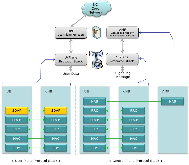 https://www.sharetechnote.com/html/5G/5G_RadioProtocolStackArchitecture.html
User Plane Protocol Stack in 5G
- The 5G protocol stack introduces SDAP (Service Data Adaptation Protocol) as a new layer within the User Plane.
- This layer is responsible for mapping application data to QoS flows, ensuring the quality of service (QoS) requirements for different applications.
5G Architecture and Protocol Stack Overview
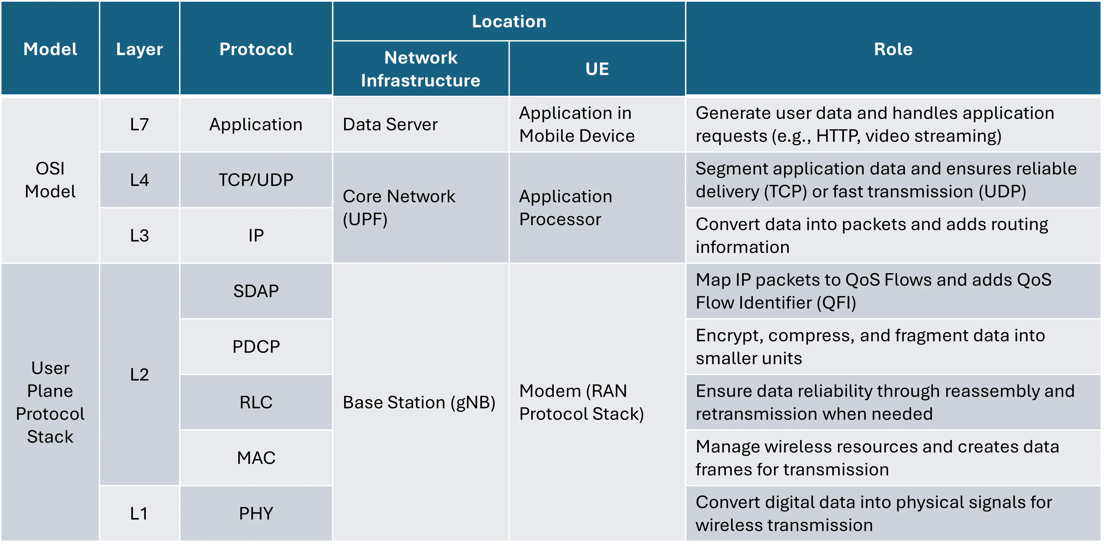
Application Data Flow in 5G User Plane Protocol Stack
Message Flow (Uplink)
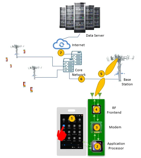
The following diagram illustrates the Uplink Message Flow in the 5G system:
 https://www.sharetechnote.com/html/5G/5G_RadioProtocolStackArchitecture.html
- Application Layer
- The data generation phase.
- When a user executes an application and requests data, the application layer generates data corresponding to that request .(e.g., HTTP requests or video files)
- Application Processor
- Ensures data reliability and routing.
- Encapsulates application data into TCP/UDP segments.
- Creates IP packets and delivers them to the modem.
- Modem
- The SDAP layer maps IP packets to the appropriate QoS Flow.
- Processes data through the PDCP → RLC → MAC → PHY layers for physical transmission.
- RF Frontend
- Converts PHY-layer processed data into wireless signals for transmission through the RF frontend.
- Sends the wireless signal to the base station (gNB).
- Base Station (gNB)
- Processes received data through the PHY → MAC → RLC → PDCP → SDAP layers.
- Forwards the processed data to the Core Network.
- Core Network
- The UPF (User Plane Function) manages data flows
- TCP ensures reliability by:
- Verifying packet integrity via ACK responses.
- Reassembling TCP segments into application data.
- Routes IP packets to the Data Server.
- Internet → Data Server
- The final destination.
- Processes the data at the server’s Application Layer.
Data Flow: Sender Perspective
1. Application Layer
- Data generation: Handles incoming or outgoing data requests and creates the payload to be sent.
2. TCP Layer
- Divides the payload into segments that fit within the available Send Window and Maximum Segment Size (MSS).
- Adds a TCP header to each segment before forwarding it to the IP layer.
3. IP Layer
- IP Fragmentation: If the segment from the TCP layer exceeds the MTU (Maximum Transmission Unit), the IP layer splits it into smaller fragments.
- Efficiency Concerns: Fragmentation introduces additional IP headers for each fragment, increasing overhead.
- If any fragment is lost, the entire segment must be retransmitted by the TCP layer, causing performance degradation.
- To avoid fragmentation, Dynamic Path MTU Discovery adjusts the MSS (Maximum Segment Size) dynamically based on the MTU of the network path.
- Each fragment is encapsulated with an IP header and passed to the SDAP layer for further processing.
4. SDAP (Service Data Adaptation Protocol) Layer
QoS Flow Mapping
- The SDAP layer maps application data to the appropriate QoS Flow based on its QoS Flow Identifier (QFI).
- Each QFI corresponds to a specific QoS profile that defines requirements like:
- Latency.
- Throughput.
- Reliability.
- Each QFI corresponds to a specific QoS profile that defines requirements like:
- The mapping ensures that application data is transmitted according to its specific QoS requirements.
SDAP Header Addition
- The SDAP layer adds an SDAP header to the data, which includes the QFI.
- QFI identifies the QoS flow for the data.
- This ensures the correct QoS treatment as the data moves through the protocol stack.
DRB Mapping
- The SDAP layer maps each QoS flow to a specific Data Radio Bearer (DRB).
- A single DRB may serve multiple QoS flows, but this depends on the QoS profiles and network configuration.
- DRB mapping ensures that data is carried through the correct logical channel in the RLC layer.
Data Forwarding
- Once the SDAP header is attached and QoS mapping is complete:
- The SDAP layer delivers the SDAP SDU to the PDCP Layer for further processing (e.g., encryption, compression).
5. PDCP (Packet Data Convergence Protocol) Layer
Header Compression
- Compresses upper-layer headers (e.g., TCP, IP, SDAP) using ROHC (Robust Header Compression).
- This minimizes the size of the headers, improving transmission efficiency and conserving bandwidth.
Data Encryption and Integrity Protection
- Encryption:
- Encrypts the payload using standard algorithms such as AES (Advanced Encryption Standard) or SNOW 3G.
- The encryption key is derived from security keys (e.g., K_RRC or K_UP) established during the RRC security procedure.
- Integrity Protection:
- Generates a HMAC (Hash-based Message Authentication Code) to ensure the integrity of the entire PDCP PDU.
- The HMAC guarantees that the data has not been altered during transmission.
- Integrity keys are derived through the same key derivation process used for encryption.
PDCP Header Addition
- Adds the PDCP header, which contains critical information such as sequence numbers for reordering and retransmission.
PDCP PDU Structure
- The resulting PDCP PDU (Protocol Data Unit) comprises:
- PDCP Header
- Compressed Upper-layer Headers (TCP/IP/SDAP)
- Encrypted Payload
- HMAC for Integrity Protection
After processing, the PDCP PDU is delivered to the RLC layer for further segmentation and transmission.
6. RLC (Radio Link Control) Layer
Transmission Modes
- The RLC layer supports three modes tailored to different application requirements:
- Transparent Mode (TM):
- No segmentation or retransmission.
- Primarily used for broadcasting system messages.
- Unacknowledged Mode (UM):
- Segments and transmits data without retransmission.
- Suitable for low-latency applications like video streaming, VoIP, or online gaming.
- Acknowledged Mode (AM):
- Ensures reliable transmission with ACK/NACK-based retransmission.
- Segments data and retransmits lost packets based on Poll Trigger mechanisms.
- Typically used for applications requiring high reliability, such as file transfers or VoLTE.
- Transparent Mode (TM):
Segmentation and Concatenation
- Segmentation:
- When the PDCP SDU size exceeds the TBS (Transport Block Size) requested by the MAC layer, the RLC layer splits the SDU into smaller RLC PDUs.
- Sequence numbers (SNs) are assigned to each PDU for ordering.
- Concatenation:
- If the PDCP SDU size is smaller than the requested TBS, the RLC layer concatenates multiple SDUs into a single RLC PDU.
- This ensures efficient use of resources and reduces header overhead.
Acknowledgment Mechanism (AM Mode)
- Poll Trigger:
- The sender periodically triggers acknowledgments by setting the Poll Bit in the RLC header.
- Poll Trigger can occur based on:
- The number of transmitted RLC PDUs.
- The total size of transmitted data exceeding a predefined threshold.
- Upon receiving a PDU with the Poll Bit set, the receiver generates a Status PDU containing ACK/NACK information for received or missing RLC PDUs.
- Retransmission:
- If a NACK or no response is received within the t-PollRetransmit timer, the sender retransmits the corresponding RLC PDUs.
- This mechanism ensures reliability without excessive overhead.
RLC Header
- Includes critical information:
- Sequence Number (SN): Identifies the order of PDUs.
- Segmentation Info: Specifies the start and end of fragmented data.
- Polling Bit: Triggers acknowledgment responses in AM mode.
Interaction with MAC Layer
- The RLC layer prepares PDUs based on the TBS provided by the MAC layer.
- Dynamically performs segmentation or concatenation to match the requested TBS.
Final Output
- The RLC layer sends RLC PDUs to the MAC layer, optimized for efficient transport while maintaining reliability and flow control in AM mode.
7. MAC (Medium Access Control) Layer
Resource Scheduling
- Manages logical channel priorities based on QoS requirements.
- Allocates resources to each logical channel based on:
- Buffer status reports (BSR) from RLC.
- QoS flow requirements (e.g., 5QI - 5G QoS Identifier).
- Channel conditions reported by PHY (e.g., CQI - Channel Quality Indicator).
Interaction with PHY for TBS
- The MAC layer requests resources from the PHY layer based on data buffer status and QoS requirements.
- The PHY layer calculates the Transport Block Size (TBS) based on:
- Allocated resource blocks (RBs).
- Modulation and Coding Scheme (MCS).
- Channel conditions.
- The PHY layer provides the calculated TBS back to the MAC layer.
Segmentation and Padding
- The MAC layer ensures data fits within the TBS provided by the PHY layer:
- Segments RLC PDUs if the data size exceeds the TBS.
- Adds padding if the data size is smaller than the TBS, ensuring efficient utilization of resources.
- Triggered by Scheduling:
- These operations are a direct result of scheduling decisions, where the MAC layer determines how to distribute the available TBS among multiple RLC flows based on their priorities
MAC Header
- Adds a MAC header containing:
- Logical Channel ID (LCID) to identify the source of the data.
- Length fields indicating the size of each data segment.
- Control information such as BSR or Power Headroom Report (PHR).
Final Interaction with PHY
- The MAC layer delivers the prepared MAC PDU (including header and payload) to the PHY layer for transmission.
8. PHY (Physical) Layer
Resource Allocation and Mapping
- Maps data onto physical resources in the time domain (slots) and frequency domain (resource blocks, RBs).
- Uses OFDM (Orthogonal Frequency Division Multiplexing) to efficiently transmit data over multiple subcarriers.
Transport Block Size (TBS) Calculation
- The PHY layer calculates the TBS based on the following parameters:
-
Modulation and Coding Scheme (MCS): Determines the number of bits per symbol.
-
Number of Resource Blocks (RBs): Allocated by the MAC layer based on CQI (Channel Quality Indicator).
-
Code Rate (R): Represents the ratio of information bits to total bits transmitted.
-
Formula:
- : Code rate (e.g., 1/3, 2/3).
- : Bits per modulation symbol (e.g., 2 for QPSK, 4 for 16QAM, 6 for 64QAM).
- : Number of allocated RBs × OFDM symbols.
-
- Reports the calculated TBS to the MAC layer.
Modulation and Channel Coding
- Modulation: Converts digital data (bits) into analog symbols using modulation schemes like QPSK, 16QAM, or 64QAM.
- Channel Coding: Applies FEC (Forward Error Correction) to improve transmission reliability.
- Uses advanced coding techniques like LDPC (Low-Density Parity Check) for eMBB and Polar Codes for URLLC.
Beamforming and MIMO
- Beamforming: Focuses the signal in a specific direction for enhanced signal strength and reduced interference.
- MIMO (Multiple-Input Multiple-Output): Increases spectral efficiency by transmitting multiple data streams simultaneously.
Interaction with MAC
- Receives TBS and resource allocation requests from the MAC layer.
- Provides feedback on channel conditions via CQI reports to optimize resource allocation and modulation.
Transmission
- Converts the transport block into radio signals and transmits them via antennas.
Data Flow: Receiver Perspective
1. PHY Layer
Signal Reception
- Captures OFDM signals transmitted through antennas.
OFDM Signal Restoration
- Resource Block (RB) demapping: Maps OFDM symbols back to their respective time and frequency resources.
- Fast Fourier Transform (FFT): Converts analog OFDM signals into digital symbols for further processing.
Demodulation and Decoding
- Demodulation: Converts symbols to bits using the modulation scheme (e.g., QPSK, 16QAM).
- Channel Decoding: Applies error correction coding (e.g., LDPC or Turbo coding) to restore the original data.
HARQ Processing
- Checks for errors and sends either ACK (acknowledgment) or NACK (negative acknowledgment) to the sender.
- Performs soft combining, leveraging previous transmissions to improve decoding success.
Passes the decoded Transport Block (TB) to the MAC layer.
2. MAC Layer
- MAC PDU Decoding:
- Analyzes the MAC header to identify:
- Logical Channel ID (LCID) for flow identification.
- Length for the size of each logical channel data.
- Extracts control information (e.g., Buffer Status Reports, Power Headroom Reports).
- Analyzes the MAC header to identify:
- Padding Removal: Eliminates padding from unused TBS space.
- Distributes logical channel data to respective RLC entities.
3. RLC Layer
RLC PDU Reception and Processing
- Receiving RLC PDUs from MAC Layer:
- The RLC layer receives data from the MAC layer.
- The received data can be:
- A complete RLC PDU: If the PDU is received fully, it is processed immediately.
- A partial RLC PDU: If the PDU is fragmented, the RLC layer waits for the remaining fragments to complete it.
Reassembly Mechanism
- Fragment Processing:
- The RLC layer checks if the received PDU contains Segmentation Information:
- Complete PDU: Directly forwarded to the upper layer (PDCP).
- Fragmented PDU: Uses segmentation flags (start/end flags) to determine how to reassemble the fragments.
- The RLC layer checks if the received PDU contains Segmentation Information:
- T-Reassembly Timer Activation:
- When only part of a PDU or sequence is received, the T-Reassembly Timer is triggered.
- Timer behavior:
- During Timer Activation:
- If the remaining fragments or PDUs are received before the timer expires, the RLC layer reassembles the complete SDU and forwards it to the PDCP layer.
- When the Timer Expires:
- If the reassembly is incomplete, the RLC layer either:
- Discards the incomplete data, or
- Forwards it to the upper layer (PDCP), depending on the implementation or transmission mode.
- If the reassembly is incomplete, the RLC layer either:
- During Timer Activation:
Sequence Management and Alignment
- Sequence Number-Based Ordering:
- Each RLC PDU includes a Sequence Number (SN).
- The RLC layer uses these SNs to ensure the correct order of data before forwarding it to the PDCP layer.
- If out-of-order PDUs are detected:
- Missing SNs are identified, and the T-Reassembly Timer is activated to wait for the missing data.
- Once the sequence is complete or the timer expires, the RLC layer processes the data accordingly.
Behavior Based on Transmission Mode
- Transparent Mode (TM):
- No sequence management or reassembly is performed.
- Data is forwarded to the upper layer as-is, typically used for broadcast messages (e.g., system information).
- Unacknowledged Mode (UM):
- Data is transmitted without retransmissions.
- Missing PDUs are discarded, and only received data is forwarded to the PDCP layer.
- Acknowledged Mode (AM):
- Ensures reliable delivery through retransmissions.
- The receiver responds to polling from the sender by sending a Status PDU containing ACK/NACK information.
- If missing PDUs are detected, the receiver requests retransmission.
Final Data Handling
- RLC SDU Delivery:
- The RLC layer forwards complete SDUs to the upper layer (PDCP), ensuring data integrity.
- In cases of incomplete data (e.g., timer expiration), the RLC layer processes it according to the transmission mode and implementation.
- PDU Sequence Restoration:
- In AM and UM modes, reorders data using Sequence Numbers (SN).
- Waits for missing data using a T-Reassembly timer.
- Segmentation and Reassembly:
- Reassembly: Combines fragmented RLC PDUs into the original PDCP SDUs.
- Segmentation: Splits large PDCP SDUs if needed.
- Passes the reassembled PDCP SDUs to the PDCP layer.
4. PDCP Layer
Sequence Reordering
- The PDCP layer restores the correct order of data using Sequence Numbers (SNs) received from the RLC layer.
- Data from the RLC layer may arrive out of order; the PDCP layer reorders this data into a single, correctly ordered sequence.
- Once reordering is complete, the sequence forms a single PDCP PDU, which is processed further.
Header Decompression
- The PDCP layer uses ROHC (Robust Header Compression) to reconstruct the original TCP/IP headers from the compressed headers received.
Decryption and Integrity Verification
- Decryption:
- The PDCP layer decrypts the data payload to restore its original state.
- Decryption uses keys derived during the security procedure (e.g., K_UP).
- Integrity Verification:
- Validates the data’s integrity using Message Authentication Code for Integrity (MAC-I).
- If the integrity check fails, the data is discarded.
Delivery to SDAP Layer
- The PDCP layer delivers the fully restored PDCP PDU to the SDAP layer for QoS flow processing.
5. SDAP Layer
QoS Flow Identification
- The SDAP layer extracts the QoS Flow Identifier (QFI) from the received PDCP PDU header.
- Each QFI is mapped to a specific Data Radio Bearer (DRB), which is associated with a QoS flow.
Mapping Data to QoS Flows
- The SDAP layer identifies which QoS flow the data belongs to using the extracted QFI.
- It classifies and groups incoming PDCP PDUs that belong to the same QoS flow.
Reordering Across DRBs
- If multiple DRBs are active, the SDAP layer ensures the correct order of data within each DRB.
- Data from different DRBs is processed independently based on their respective QoS requirements.
Handling QoS Policies
- The SDAP layer applies QoS policies (e.g., latency, throughput, reliability) to manage traffic prioritization and scheduling for each DRB.
Delivery to IP Layer
- Once the data is classified and processed, the SDAP layer forwards the SDAP SDUs to the IP layer for further protocol stack processing.
6. IP Layer
- IP Header Restoration: Reconstructs the IP header.
- Fragment Reassembly: Combines fragmented packets into complete IP packets.
- Protocol Identification: Identifies whether the data belongs to TCP or UDP.
- Forwards the packet to the TCP layer.
7. TCP Layer
- Segment Sequence Restoration:
- Reorders TCP segments using Sequence Numbers.
- Integrity Check: Verifies segment integrity using checksum.
- ACK Transmission:
- Sends an ACK to the sender for successfully received data.
- Segment Reassembly: Combines TCP segments into the original data stream.
- Passes the complete data stream to the Application Layer.
8. Application Layer
- Processes the received data and generates appropriate responses.
Retransmission Mechanisms Across Layers
1. PHY/MAC Layers
- Retransmission Unit: Transport Block (TB).
- Retransmission Protocol: HARQ (Hybrid Automatic Repeat Request).
- The PHY layer handles retransmissions of TBs based on ACK/NACK responses from the receiver.
- Soft Combining: Combines previously received TB data with newly received retransmissions to improve decoding success.
- HARQ operates with low latency (few milliseconds) to ensure rapid retransmission and recovery.
Sender Perspective
- HARQ Process Management:
- The sender retains each TB in the HARQ buffer until it receives an ACK or NACK from the receiver.
- If a NACK is received, the sender retransmits the TB.
- Soft Combining Support:
- Retransmitted data is encoded to allow the receiver to combine it with previously received data fragments, improving the decoding success rate.
Receiver Perspective
- ACK/NACK Generation:
- After decoding a TB, the receiver sends an ACK (if successful) or a NACK (if errors are detected) to the sender.
- Soft Combining at Receiver:
- The receiver combines retransmitted data with previous TB fragments to maximize decoding performance.
2. RLC Layer
- Retransmission Unit: RLC PDU.
- Retransmission Protocol: ACK/NACK-based Polling Mechanism (AM Mode).
- The RLC layer periodically triggers Poll Requests to check the status of transmitted PDUs
- The receiver sends the Status PDU, which includes ACK/NACK information for each RLC PDU.
Sender Perspective
- Polling Mechanism:
- The sender periodically triggers a Poll PDU by setting the Poll Bit in the RLC header to request a Status PDU from the receiver.
- t-PollRetransmit Timer:
- If no response is received within the timer, the sender retransmits the PDUs identified as missing.
- Retransmission Management:
- The sender retransmits PDUs marked as NACK in the received Status PDU.
Receiver Perspective
- Status PDU Generation:
- The receiver maintains a bitmap of received RLC PDUs and responds to Poll PDUs by sending a Status PDU containing ACK/NACK information.
3. PDCP Layer
- Retransmission Unit: PDCP PDU.
- Retransmission Protocol: STATUS REPORT-based Mechanism (Optional).
- The receiver uses Sequence Numbers (SNs) to track missing PDCP PDUs.
- If a missing PDU is detected, the receiver generates a STATUS REPORT requesting retransmission.
- The sender retransmits the requested PDCP PDUs based on the STATUS REPORT.
- PDCP retransmission is generally used in conjunction with Unacknowledged Mode (UM) at the RLC layer to enhance reliability.
Sender Perspective
- Sequence Number Management:
- The sender tracks all transmitted PDCP PDUs using sequence numbers.
- Retransmission Trigger:
- If a STATUS REPORT is received from the receiver indicating missing PDUs, the sender retransmits them.
Receiver Perspective
- STATUS REPORT Generation:
- The receiver generates a STATUS REPORT based on missing PDUs identified through sequence numbers.
- Reordering:
- The receiver reorders out-of-sequence PDUs to ensure data consistency before forwarding them to the upper layers.
4. TCP Layer
- Retransmission Unit: TCP Segment.
- Retransmission Protocol: ACK-based Mechanism.
- TCP ensures reliability using an acknowledgment system:
- ACK: Sent by the receiver to confirm successful delivery of data.
- Timeout-based Retransmission: If an ACK is not received within the Retransmission Timeout (RTO), the sender retransmits the segment.
- Duplicate ACKs: When the receiver sends multiple ACKs for the same data (e.g., due to packet loss), the sender performs Fast Retransmission.
- TCP retransmission operates end-to-end, independently of lower-layer retransmission mechanisms.
- TCP ensures reliability using an acknowledgment system:
Sender Perspective
- Retransmission Trigger:
- Retransmission occurs if:
- An ACK is not received within the Retransmission Timeout (RTO).
- Duplicate ACKs indicate packet loss.
- Retransmission occurs if:
- Fast Retransmission:
- The sender retransmits a segment without waiting for the RTO if multiple duplicate ACKs are received.
Receiver Perspective
- ACK Generation:
- The receiver sends an ACK for successfully received segments.
- Duplicate ACKs:
- If out-of-order segments are received, the receiver sends duplicate ACKs to signal missing data.
- Out-of-Order Handling:
- The receiver buffers out-of-order segments while waiting for missing ones to complete the sequence
Potential Overlaps Between Layers
PHY/MAC vs. RLC
- Retransmission Overlap Possibility: None
- Reason:
- PHY/MAC layers handle retransmissions immediately (via HARQ), completing the process before RLC’s periodic retransmissions are triggered by Polling PDUs.
- Even in scenarios involving Polling PDUs, the process flow ensures no overlap occurs.
Polling PDU Scenario
- An RLC Polling PDU is segmented into two MAC PDUs.
- One MAC PDU is successfully delivered, while the other fails.
- The first MAC PDU is processed by RLC, but the second is retransmitted via HARQ.
Why Overlap Does Not Occur
- The second MAC PDU, containing part of the RLC Polling PDU, fails and triggers a NACK at the PHY layer.
- HARQ retransmits the failed MAC PDU before RLC’s t-PollRetransmit timer expires.
- RLC processes a complete RLC PDU only after all associated MAC PDUs are successfully received.
- RLC generates a Status PDU in response to a Polling PDU only after the Polling PDU has been fully received at the PHY/MAC layer.
RLC vs. PDCP
- Retransmission Overlap Possibility: There may be overlapping retransmission requests, but actual retransmissions are not duplicated.
- Reason: The layered structure and prioritization ensure that only one layer handles the retransmission at a time.
- Overlapping Retransmission Requests Cases:
- PDCP sends a STATUS REPORT first, followed by RLC Poll PDU.
- RLC sends a STATUS PDU first, but incomplete sequences trigger a PDCP STATUS REPORT later.
Case 1: PDCP STATUS REPORT First
- Scenario:
- PDCP detects missing PDUs and sends a STATUS REPORT to the sender.
- Subsequently, RLC Poll PDU triggers a Status PDU requesting retransmission for the same data.
- Handling:
- The sender prioritizes the PDCP’s retransmission request, as it is processed at a higher layer.
- RLC’s retransmission request for the same data is ignored
Case 2: RLC STATUS PDU First
- Scenario:
- RLC sends a STATUS PDU after detecting missing PDUs via Poll PDU.
- Meanwhile, incomplete sequences are passed to the PDCP layer due to T-Reassembly Timer expiration.
- The PDCP layer identifies the same missing PDUs and sends a STATUS REPORT.
- Handling:
- The sender prioritizes retransmissions triggered by RLC, as they occur at a lower layer.
- PDCP STATUS REPORT requests for overlapping data are ignored.
PDCP vs. TCP
- Retransmission Overlap Possibility: Exists due to the separate and independent mechanisms of TCP and PDCP.
- Reason:
- PDCP operates at the wireless link, where the receiver triggers retransmissions based on missing PDUs.
- TCP operates end-to-end, where the sender triggers retransmissions based on ACK timeouts or duplicate ACKs.
- Neither layer coordinates its retransmission logic, making overlap more likely.
Detailed Explanation
- How Each Layer Handles Retransmissions:
- PDCP:
- Ensures reliability in the wireless environment by allowing the receiver to request retransmissions via STATUS REPORTs.
- Decisions are localized to the wireless segment of the network and focus on compensating for radio link errors.
- TCP:
- Provides end-to-end reliability by retransmitting segments based on:
- Retransmission Timeout (RTO) if ACKs are delayed or missing.
- Fast Retransmission upon receiving multiple duplicate ACKs.
- Provides end-to-end reliability by retransmitting segments based on:
- PDCP:
- Independent Judgment:
- PDCP Receiver:
- Detects missing PDUs and requests retransmissions.
- TCP Sender:
- Observes end-to-end conditions and retransmits based on segment-level acknowledgment failures.
- PDCP Receiver:
- Why Overlap Risk is High:
- Receiver-Side (PDCP) vs. Sender-Side (TCP):
- PDCP retransmissions are decided by the receiver (localized to the wireless link).
- TCP retransmissions are decided by the sender (based on global, end-to-end feedback).
- These independent layers cannot coordinate or cancel duplicate retransmission requests.
- Receiver-Side (PDCP) vs. Sender-Side (TCP):
Issues with Overlap
- Resource Wastage:
- Both layers retransmit the same data redundantly, consuming unnecessary network and processing resources.
- Increased Latency:
- Redundant retransmissions delay overall delivery of data to the application.
Solutions
- Disable PDCP Retransmissions for TCP Traffic:
- For TCP-based services (e.g., eMBB), rely solely on TCP retransmissions.
- Enable PDCP Retransmissions for UDP Traffic:
- For latency-sensitive applications (e.g., VoIP), enable PDCP retransmissions to compensate for UDP’s lack of reliability.
- Timer Adjustment (Hybrid):
- For services like URLLC, configure PDCP timers (e.g., T-Status-Prohibit) to expire faster than TCP timeouts, ensuring efficient retransmissions without overlap.
References
- 3GPP TS 38.322: Radio Link Control (RLC) Protocol Specification, 3GPP Release 17, 3rd Generation Partnership Project (3GPP). Available at: https://www.3gpp.org/ftp/Specs/archive/38_series/38.322/
- Key Sections Referenced:
- Section 5.3: Data Transfer Services and Functions (segmentation and reassembly).
- Section 6.1: Protocol Data Units (PDUs) (ACK/NACK handling, Polling mechanism).
- Section 6.1.3: Timers (t-PollRetransmit and reassembly logic).
- Key Sections Referenced:
- 3GPP TS 38.323: Packet Data Convergence Protocol (PDCP) Specification, 3GPP Release 17, 3rd Generation Partnership Project (3GPP). Available at: https://www.3gpp.org/ftp/Specs/archive/38_series/38.323/
- Key Sections Referenced:
- Section 5.2: Sequence Number Management (STATUS REPORT-based retransmissions).
- Section 6.2: PDCP PDU Formats (handling retransmissions and STATUS REPORTs).
- Section 6.3: Timers (e.g., T-Status-Prohibit).
- Key Sections Referenced:
- 3GPP TS 38.331: Radio Resource Control (RRC) Protocol Specification, 3GPP Release 17, 3rd Generation Partnership Project (3GPP). Available at: https://www.3gpp.org/ftp/Specs/archive/38_series/38.331/
- Key Sections Referenced:
- Section 5.3.3: RRC Procedures for Configuration (retransmission-related parameter settings).
- Section 6.3: RRC Messages (interaction between RRC and retransmission mechanisms).
- Key Sections Referenced:
- 3GPP TS 36.300: Evolved Universal Terrestrial Radio Access (E-UTRA) and Evolved Universal Terrestrial Radio Access Network (E-UTRAN); Overall Description, 3GPP Release 15, 3rd Generation Partnership Project (3GPP). Available at: https://www.3gpp.org/ftp/Specs/archive/36_series/36.300/
- Key Sections Referenced:
- Section 6.5: HARQ Operations in LTE (conceptual references for HARQ in NR).
- Section 10.1: Retransmission Mechanisms in LTE (framework carried forward to 5G NR).
- Key Sections Referenced:
- RFC 793: Transmission Control Protocol (TCP) Specification, Internet Engineering Task Force (IETF), September 1981. Available at: https://www.rfc-editor.org/rfc/rfc793
- Key Sections Referenced:
- Section 3.2: Retransmission Timeout (RTO) and acknowledgment mechanisms.
- Section 3.7: Sliding Window and Data Sequencing (basis for TCP retransmissions).
- Key Sections Referenced:
- RFC 1191: Path MTU Discovery, Internet Engineering Task Force (IETF), November 1990. Available at: https://www.rfc-editor.org/rfc/rfc1191
- Key Sections Referenced:
- Section 4: Fragmentation Avoidance with MTU Discovery (dynamic MSS adjustment).
- Section 6: PMTUD Mechanism Details (protocol-level adaptation).
- Key Sections Referenced:
- RFC 4821: Packetization Layer Path MTU Discovery, Internet Engineering Task Force (IETF), March 2007. Available at: https://www.rfc-editor.org/rfc/rfc4821
- Key Sections Referenced:
- Section 3: Dynamic Path MTU Updates (integrated PMTUD for modern networks).
- Section 5: Interaction with TCP and UDP (layer-specific PMTUD strategies).
- Key Sections Referenced: